
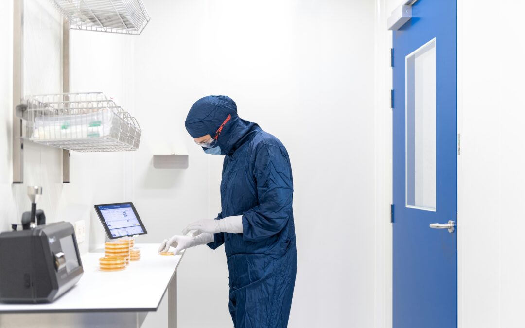
The airlock is one of the most critical yet frequently underestimated elements in cleanroom design. Its primary function is straightforward: to create a controlled transition zone between areas of different cleanliness classifications, preventing uncontrolled air movement and particle migration during personnel and material entry and exit. In practice, however, the design of a cleanroom airlock involves a precise interplay of pressure differentials, interlock sequences, airflow management, and compliance documentation – all of which must be defined, validated, and maintained throughout the facility’s operational life.
In GMP-regulated pharmaceutical manufacturing, the airlock is not merely a spatial buffer. It is a functional component of the facility’s Contamination Control Strategy (CCS), as defined under EU GMP Annex 1 (2022 revision). Its correct design contributes directly to the integrity of the classified area it protects and to the traceability of contamination control measures during regulatory inspections.
What Is a Cleanroom Airlock and Why It Matters
A cleanroom airlock is an enclosed space positioned between two areas of different ISO classification or cleanliness grade, equipped with interlocked doors on both sides to prevent simultaneous opening. Its purpose is to buffer air exchange between the two areas: rather than allowing direct communication between, for example, a Grade C corridor and a Grade B production room, personnel and materials pass through the airlock, which acts as a pressure and particle barrier.
The airlock matters because air movement is the primary mechanism of particle and microorganism transport in a cleanroom environment. Each time a door opens, a volume of air flows from the higher-pressure area toward the lower-pressure area, carrying with it particles from the space it originated in. An airlock with properly maintained pressure differential and interlock system controls this exchange, limiting the particle load introduced into the classified area to the minimum achievable under dynamic conditions.
The importance of this function scales with the classification gradient across the boundary. A transition from ISO Class 8 to ISO Class 7 carries a lower risk than a transition from Grade C to Grade A/B, where the airlock must provide a robust barrier against both particles and viable microorganisms. In aseptic filling environments, a poorly designed airlock can undermine the entire contamination control architecture of the facility, regardless of the quality of the equipment installed inside the production room.
Pressure Cascade Design in Cleanroom Airlocks
Pressure cascade is the foundational design principle governing airlock function. The core rule is that air flows from cleaner areas toward less clean areas — meaning higher-pressure zones push air outward, preventing particles from the lower-classification area from entering the higher-classification space.
In a typical pharmaceutical cleanroom layout, the pressure hierarchy might follow:
Grade A/B (ISO 5) > Grade C (ISO 7) > Grade D (ISO 8) > Unclassified corridor
Each boundary between zones is managed by a pressure differential, typically 10–15 Pa. The airlock itself must be maintained at a pressure intermediate between the two spaces it connects. In a bubble airlock (positive pressure airlock), the airlock is maintained at higher pressure than both adjacent areas, so air flows outward on both sides. This configuration protects the classified area from particle ingress from the corridor and simultaneously prevents contaminated air from the corridor from entering. The bubble configuration is standard for transitions into aseptic Grade A/B environments.
In a sink airlock (negative pressure or cascade airlock), the airlock is maintained at lower pressure than both adjacent areas, so air flows inward from both sides. This is used where containment of a hazardous substance inside the classified area is the priority — for example, transitions in and out of areas handling cytotoxic compounds or potent active pharmaceutical ingredients. In this configuration, airlock pressure prevents outward contamination of the corridor and building.
Key design parameters include:
- Pressure differential at each door: minimum 10 Pa between zones, verified under dynamic conditions (doors closed, HVAC running)
- Door interlock system: mechanical or electromagnetic interlocks preventing simultaneous opening of both doors, with time delays allowing pressure re-establishment between opening cycles
- Air supply and exhaust positioning: supply inlets and return grilles placed to avoid short-circuiting and ensure adequate air mixing or unidirectionality within the airlock volume
- Monitoring: continuous differential pressure monitoring with visual and audible alarms, data logging for GMP audit trail requirements
Personnel vs Material Airlocks: Key Differences
Personnel airlocks and material airlocks share the same pressure management principles but differ significantly in their functional design, size, and associated equipment.
Personnel airlocks (often referred to as gowning rooms or change rooms when more elaborate) are sized to accommodate one or more operators simultaneously and include benches, gowning hooks, shoe change points, and hand hygiene stations. Their door interlock cycle must account for the time required for gowning, which may be several minutes. Personnel airlocks in high-grade environments often incorporate interlocked bench systems (the operator must cross the bench to proceed, reinforcing the physical boundary between unclassified and classified zones).
Key requirements for personnel airlocks include adequate air volume for dilution during door cycles, appropriate lighting and visibility for gowning activities, and seamless surfaces that support cleaning and disinfection without harbouring particles.
Material airlocks – also called pass-through airlocks or material transfer bays – are designed for the controlled transfer of raw materials, in-process components, or finished product between classified zones. They are typically smaller than personnel airlocks and are often equipped with pass boxes or dynamic pass-through systems built into the airlock wall itself. In high-risk environments, material airlocks may include UV-C decontamination, VHP (vaporised hydrogen peroxide) cycles, or active HEPA-filtered downflow to reduce the surface bioburden of incoming materials.
The critical difference between the two types is contamination profile: personnel are the primary source of viable contamination (skin particles, respiratory output, clothing fibres), while materials present primarily non-viable particle loads and, depending on their origin, potential cross-contamination from external environments. The airlock design must address the dominant contamination risk for each use case.
GMP Annex 1 and ISO 14644 Requirements for Cleanroom Airlocks
EU GMP Annex 1 (2022 revision) addresses airlocks within the broader framework of Contamination Control Strategy. It does not prescribe a single airlock design standard, but sets clear expectations for the function, monitoring, and documentation of pressure barriers between classified zones.
Key Annex 1 requirements relevant to airlock design include:
- Pressure differentials between adjacent areas must be defined in the CCS and maintained throughout operation, with monitoring systems providing continuous data and alarm thresholds
- Airlocks must be classified to a defined ISO grade appropriate to their function — typically one grade below the higher-classification area they serve
- Door interlock systems must prevent simultaneous opening and must be validated to demonstrate that pressure re-establishment occurs within the defined time window after each door cycle
- Material entering Grade A and Grade B environments must pass through a defined transfer process that is part of the CCS, whether via pass box, airlock, or other validated mechanism
- Environmental monitoring data from airlocks (particle counts, differential pressure logs) must be reviewed as part of the facility’s ongoing compliance programme
ISO 14644-4 (cleanroom design and construction) provides supplementary guidance on airlock sizing, air supply positioning, and pressure differential calculation. ISO 14644-3 covers the test methods used to verify differential pressure performance during qualification, including pressure recovery time after door opening – a critical parameter that must be validated under IQ/OQ protocols.
AGMM TECH Airlock Solutions for Pharma and Biotech
AGMM TECH designs and supplies airlock-integrated cleanroom equipment for pharmaceutical and biotech facilities, including pass-through airlocks, decontamination hatches, and material transfer systems that can be configured as part of a complete airlock assembly.
Equipment is fabricated in AISI 304 stainless steel with TIG-welded construction and satin scotch-brite surface finish, ensuring compatibility with standard disinfection protocols including alcohol-based agents, quaternary ammonium compounds, and oxidising agents such as hydrogen peroxide. Door interlock systems are available in mechanical and electromagnetic configurations, with adjustable time-delay cycles to support pressure re-establishment requirements defined during qualification.
Control panels are configurable with pressure monitoring ports, audible and visual alarm outputs, and Modbus TCP connectivity for integration with facility BMS or EWON Flexy remote monitoring systems. Documentation packages for IQ/OQ phases – including dimensional drawings, wiring diagrams, interlock logic descriptions, and component certificates – are provided as standard for regulated applications.
AGMM TECH works directly with engineering and qualification teams to adapt airlock configurations to project-specific pressure cascade requirements, ISO classification targets, and CCS documentation structures.
Conclusion
The cleanroom airlock is a pressure barrier, a contamination filter, and a compliance checkpoint all at once. Its design integrates structural, mechanical, and regulatory requirements that must be addressed coherently from the earliest phases of facility planning – not retrofitted after the classified area has already been defined.
Getting the airlock right means defining the correct pressure regime for each boundary (bubble or sink, depending on the contamination risk direction), selecting an interlock system that prevents simultaneous door opening while respecting the operational tempo of the facility, and validating pressure recovery time under realistic dynamic conditions. It also means classifying the airlock itself to an appropriate ISO grade, monitoring it continuously, and maintaining the supporting documentation as a living part of the facility’s Contamination Control Strategy.
For facilities subject to EU GMP Annex 1 (2022), the airlock is no longer a peripheral detail – it is a named element of the CCS that inspectors will evaluate specifically. Its pressure differentials, interlock logic, monitoring data, and qualification records are all subject to review. A facility that has documented its airlock design decisions clearly, validated them against defined acceptance criteria, and maintained a complete audit trail will be in a significantly stronger position during inspection than one that has treated the airlock as a functional afterthought.
The distinction between personnel and material airlocks, the correct interpretation of bubble vs sink pressure configurations, and the integration of monitoring data into the facility’s environmental monitoring programme are the three areas where design errors are most commonly encountered – and most consequential to correct before construction rather than after qualification failure.
For engineering teams working on new cleanroom projects or facility upgrades, AGMM TECH is available to provide technical input on airlock equipment configurations, pressure cascade integration, and IQ/OQ documentation support as part of the project engineering process.


